Next: Masks Up: Compositor Window Previous: The Temporary, Track and Contents Index
In the compositor window, Adjust camera automation and Adjust projector automation are editing tools to control operation of the camera and projector. In CINELERRA-GG's compositing pipeline, the camera determines where in the source the temporary is copied from while the projector determines where in the output the temporary is copied to (figure 2.12).
In compositing, each frame can be changed using various options and plugins, such as a color correction plugin (figure 2.13). After the image has been modified, the final image is projected to the compositor so that you now have a changed original.
When editing the camera and projector in the compositing window, the affected track will be the first track that is armed. If there are multiple video tracks, you can select one specific track for editing with a LMB click on the Arm track icon of the desired track. This is called "solo" the track. To reverse this solo-ing, LMB click on the icon again.
The purpose of the projector is to composite several sources from various tracks into one output track. The projector alignment frame is the same as the camera's viewport, except that it shows where to put the contents of each temporary on the output canvas. To get into projector editing mode, click on the Adjust projector automation icon in the Compositor toolbar. You will then see red border lines surrounding the image and 2 diagonal lines criss-crossing in the middle, displayed in the video window. The red outline indicates the size of the frame that will be sent to the Output. You can easily drag the box with LMB, moving the frame in x and y directions. When moving along the z - axis (i.e. the zoom, with SHIFT+Drag) the box exactly follows the movement and the size of the frame. After you position the video with the projector, you may next want to Adjust camera automation.
The viewport is a window on the camera that frames the area of source video. The size of the current track is used for the initial size of the viewport. A smaller viewport, for example ( 640×480), captures a smaller area; whereas a larger viewport of ( 800×600) captures a larger area. If the captured area is larger than the source video, the empty spaces will be automatically filled with blanks. To change the size and aspect ratio of the viewport (Camera ) of a single track, right-click on the track in the timeline and choose Resize Track. Here we can vary the height and base of the viewport in pixels or choose the multiplication coefficient for each side (Scale). With OK we will see the change in the Compositor window with the new dimensions reflected in the green box. We can have different size viewports for each video track on the timeline. To go back, reset the viewport to the original value. After the viewport is defined, the camera needs to be placed right above the area of interest in the source video. Operations to control the location of the camera are as follows:
When you drag over the viewport in the compositor window, it looks like you are moving the camera with the mouse. The viewport moves in the same manner.
Select the camera button to enable camera editing mode. In this mode, the guide box shows where the camera position is in relation to past and future camera positions but not where it is in relation to the source video. The green box is the Viewport; at the beginning it coincides with the size of the source frame. If we move the viewport by dragging it with LMB (moving it in x/y), the green box remains fixed to the original size but the frame is moved to the new position. A yellow frame will appear along the edges of the frame to indicate the displacement with respect to the green box; this behavior differs from that seen for the Projector. Even if we click on the z - axis (SHIFT + Drag, equivalent to the zoom), the frame narrows or widens, moving behind the yellow frame.
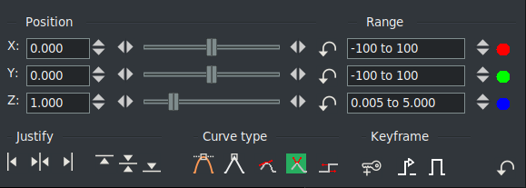
The camera and projector have shortcut operations that do not appear in the popup menu and are not represented in video overlays. These are accessed in the Show tool info window. Most operations in the Compositor window have a tool window which is enabled by activating the question mark icon (figure 2.14).
In the Position section you can change the X, Y and Z coordinates. By either tumbling or entering text directly or by using the slider, the camera and projector can be precisely positioned. There is also a reference to the color of the curve as we see it on the timeline. You can also define the range of action which by default is [-100 to 100]. By pressing the Reset button for each coordinate, or the global Reset button, the range is automatically brought to the project size value (HD; 4k; etc), which are usually the most useful limits. Note that the range can also be changed in the Program window, in the zoom bar, where there are similar input fields to enter the chosen limits.
In the Justify section we can use automatic positioning in the 6 standard coordinates: Left, Horizontal, Right, Top, Center and Bottom.
The translation effect allows simultaneous aspect ratio conversion and reduction but is easier to use if the reduced video is put in the upper left of the temporary instead of in the center. The track size is set to the original size of the video and the camera is centered. The output size is set to the reduced size of the video. Without any effects, this produces just the cropped center portion of the video in the output.
The translation effect is dropped onto the video track. The input dimensions of the translation effect are set to the original size and the output dimensions are set to the reduced size. To put the reduced video in the center subsection that the projector shows would require offsetting out X and out Y by a complicated calculation. Instead, we leave out X and out Y at 0 and use the projector's tool window. By selecting left justify and top justify, the projector displays the reduced image from the top left corner of the temporary in the center of the output.
In the Curve type section we can choose between various interpolation algorithms that determine the curve type :
In the Keyframe section we can create new keyframes and set them as Bump autos (Right/Left edges and Span buttons). For further details see Bump autos.
In the compositing window, there is a popup menu of options for the camera and projector. Right click over the video portion of the compositing window to bring up the menu:
Reset Camera: causes the camera to return to the center position.
Reset Projector: causes the projector to return to the center.
 of the original frame).
of the original frame, i.e. it has the size of the projector that has z = 0.500. This is the current viewport size.
of the original frame).
of the original frame, i.e. it has the size of the projector that has z = 0.500. This is the current viewport size.
![\includegraphics[width=0.8\linewidth]{temporary-01.pdf}](img7.gif)
![\includegraphics[width=0.8\linewidth]{camera_and_projector.pdf}](img8.gif)